I recently acquired a 3d printer and, as I was learning CAD (Computer Assisted Design), I thought about finishing a project that I had started some time ago. This article details this whole project.
At school, at work, or anywhere, really, people will at some point leave their computer unlocked and unattended. Of course, we all know that this is a bad habit and it can lead to really bad things. So when I see a friend’s computer all alone and unlocked, I make it my duty to be annoying. I will change your screen background, mouse speed or even your keyboard layout in the same amount of time an attacker would export and steal your chrome’s passwords.
So when I learned about the Rubber Ducky, I instantly knew that I could have some fun. The Rubber Ducky is a usb key, or at least it looks like one. Actually, for your computer, it’s a keyboard. And this keyboard will execute preconfigured keystrokes way faster than you could ever do.
But a Rubber Ducky costs around 80$ (not including shipping and taxes). A bit pricey for a gadget I would use very rarely. So I decided to build it myself.
Hardware
For this project, I needed a small microcontroller that I could easily connect to my computer. I choose the Raspberry Pi Pico because it has three good points for this project : it is popular, supports circuitpython, and has a nice amount of flash memory.
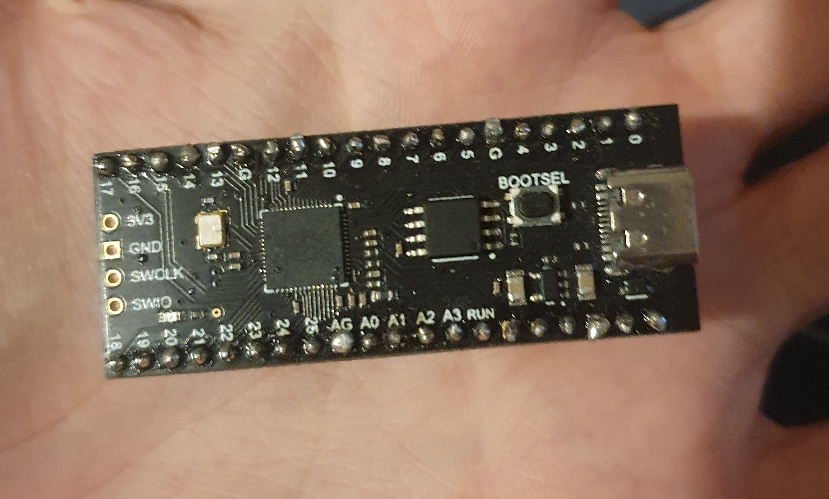 The Raspberry pi pico I bought
So I got one off Aliexpress. Actually, I got a similar board that includes a RP2040, the chip from the pico. The reason I did that is because it has USB-C and 16MB of flash memory instead of the usual 2. That way, I won’t have to worry about my scripts being too large or the port eventually giving up.
Software
CircuitPython allows user to very easily run python scripts on compatible boards. Its standard library also gives you access to very useful tools, like accessing and monitoring the GPIO pins. For a first project like this, it was a no brainer for me.
I quickly found a github repository for a tool called the pico-ducky. With it, you can “Make a cheap but powerful USB Rubber Ducky with a Raspberry Pi Pico”.
The pico-ducky software was, at the time of starting the project, not great. A lot of code was there but baddly written, not useful or just confusing. So I decided to fork it and change what I didn’t like. I also cutomized some behavior like the payload selection.
How it works
The script is quite simple, it’s goal is to interpret another script written by the user in duckyscript[^1] and emulate a keyboard. We call it the payload. Let’s look at a sample one.
DEFAULTDELAY 100
REM The next four lines open Notepad in Windows and type "Hello World!"
GUI r
STRING notepad
ENTER
DELAY 250
STRING Hello World!
This script is quite simple, here’s what it does :
- Set the default delay before commands to
100ms - Press the
Win+rtogether - Write
notepad - Hit
enter - Wait for
250ms - Write
Hello World!in the notepad you just opened
In our code, we have a simple function called parse_line to parse every single line of our script and execute the corresponding command.
def parse_line(line):
    global default_delay
    if line[0:3] == "REM":
        # ignore ducky script comments
        pass
    elif line[0:5] == "DELAY":
        # Sleep for specified number of milliseconds
        time.sleep(float(line[6:]) / 1000)
    elif line[0:6] == "STRING":
        # Type the following string
        write_string(line[7:])
    elif line[0:5] == "PRINT":
        # Print the following string to the console
        print("[SCRIPT]: " + line[6:])
    elif line[0:6] == "IMPORT":
        # Import another ducky script and run it
        run_script(line[7:])
    elif line[0:13] == "DEFAULT_DELAY":
        # Set the default delay for each command
        default_delay = int(line[14:])
    elif line[0:12] == "DEFAULTDELAY":
        # Set the default delay for each command
        default_delay = int(line[13:])
    elif line[0:3] == "LED":
        # toggle the pico led
        led.value = not led.value
    else:
        # otherwise, convert the line and run it
        new_script_line = convert_line(line)
        run_script_line(new_script_line)
Easy! Add a payload selector so that we can select and run different payloads by pressing buttons, add a keyboard emulation library and you’re done! You can check the rest of the code here if you want to see how I did that.
Case
To finish this project properly, I needed a case for the board and the buttons. I couldn’t see this project as a complete one without a way to put it in my pocket without risking of breaking it. So I got to work.
First case
I started by buying a basic case off aliexpress to experiment on. The goal was to have a working case with buttons, even though I knew it would be ugly.
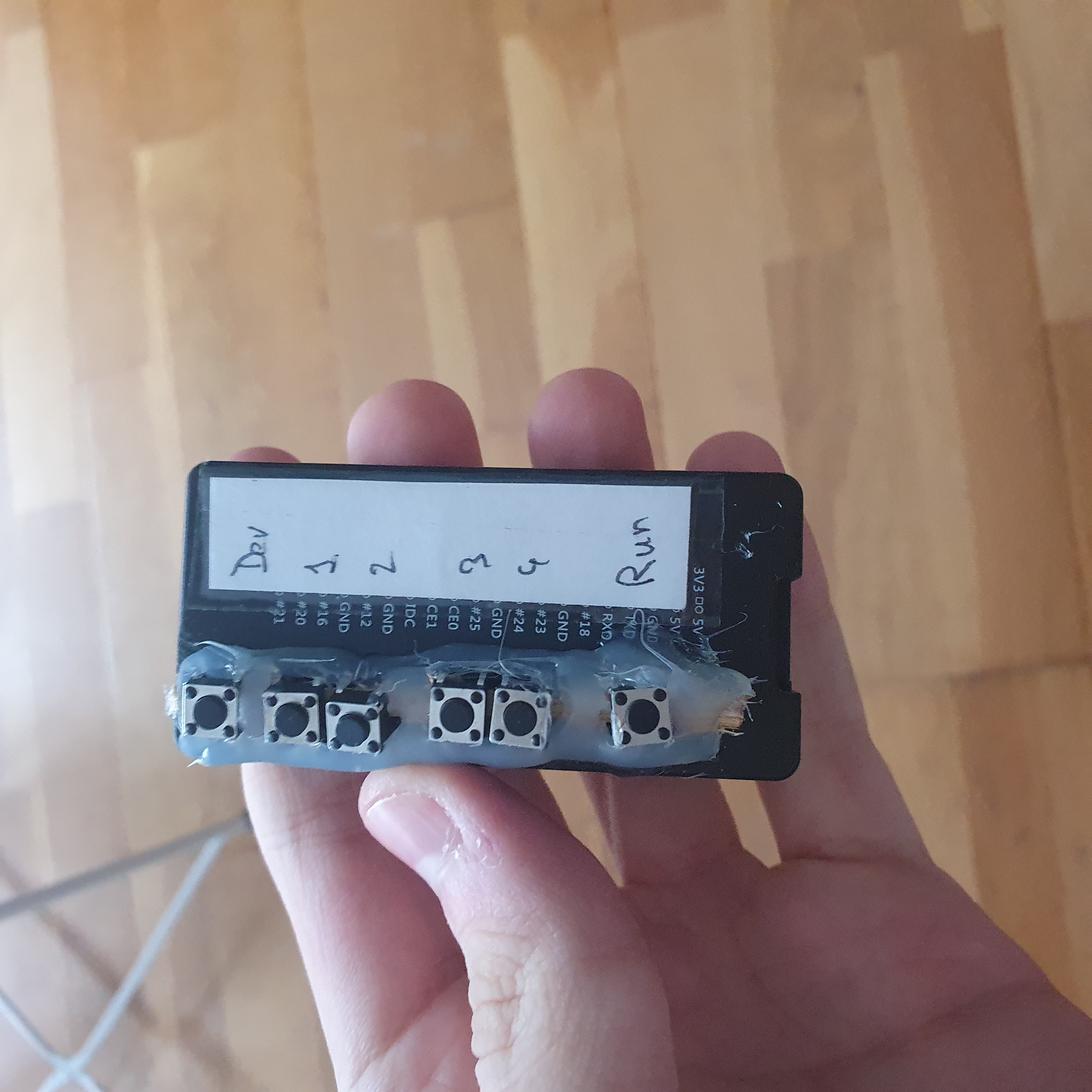 The first case I made
The hard plastic and lack of a proper place to have the buttons made it hard to work with, so I quickly used this excuse to buy a 3d printer and gave the case to a friend.
Second case
The lessons I learned from building the first case were that I needed to have proper slots for the buttons and plan their positions to make soldering easier.
I got on OnShape, my favorite CAD software and modeled a case that would fit my pico and my buttons. Here is the final version.
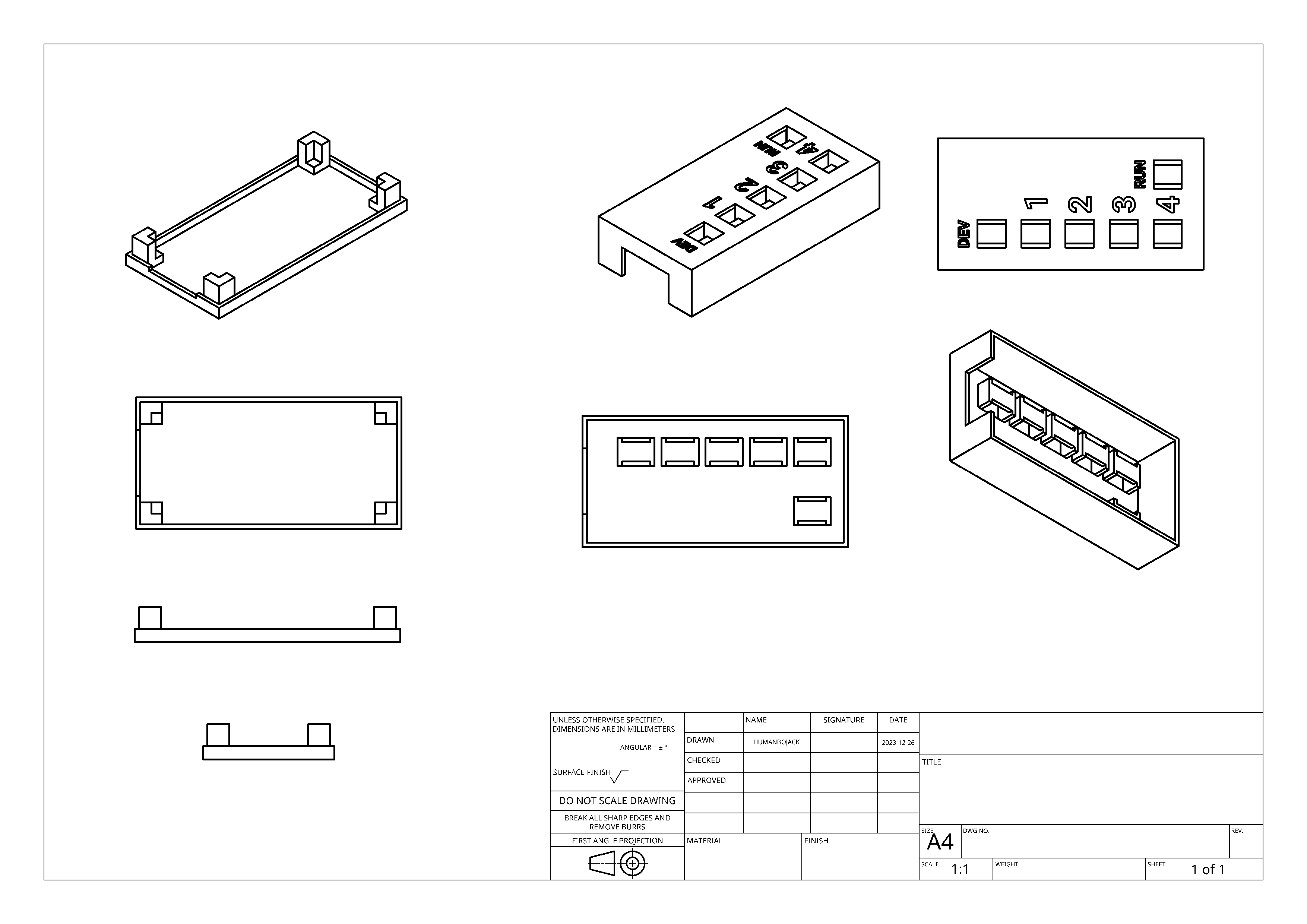 A drawing of the final version of the case (bottom is on the left and top is on the right)
 The printed bottom of the case
 The printed top of the case
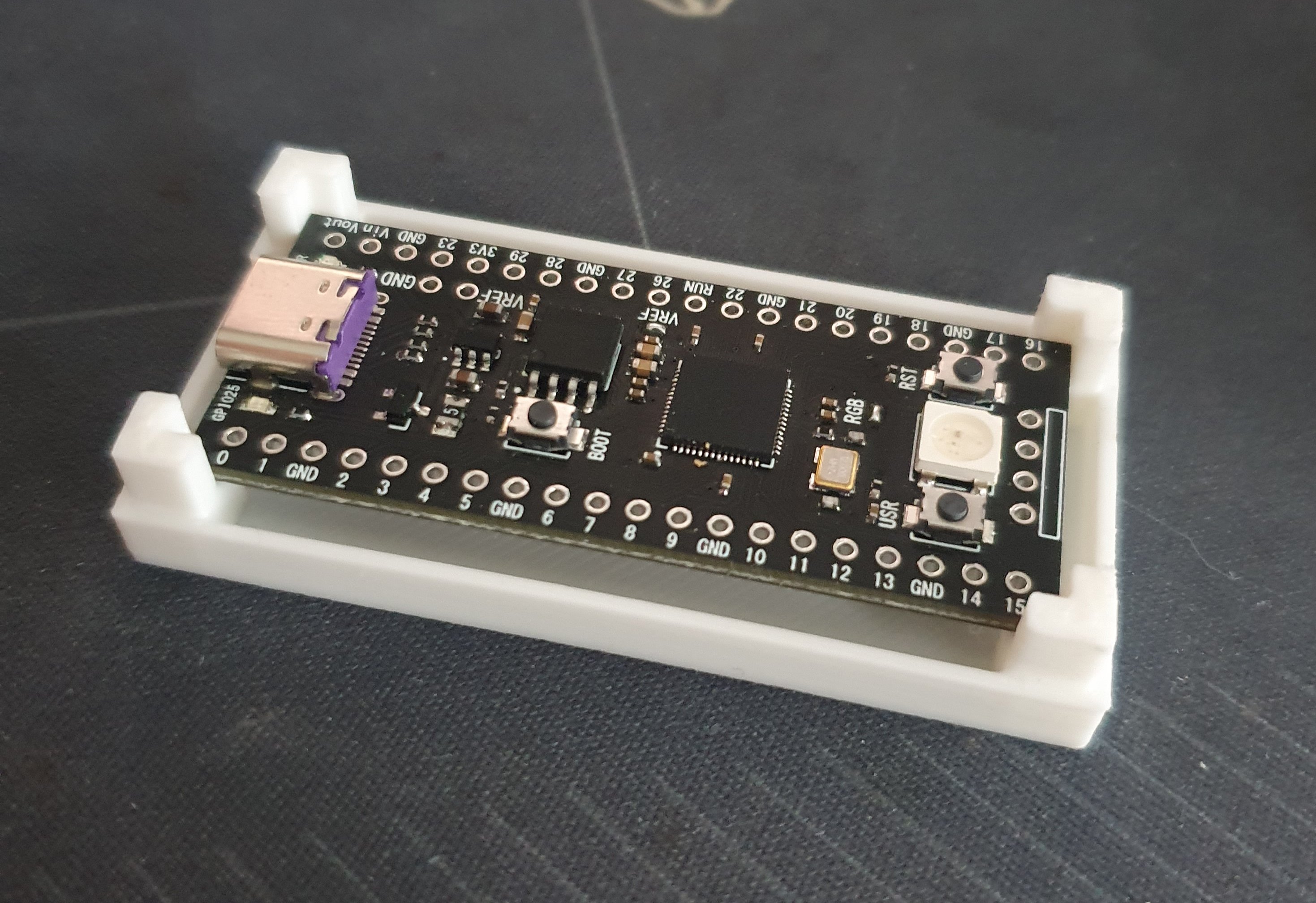
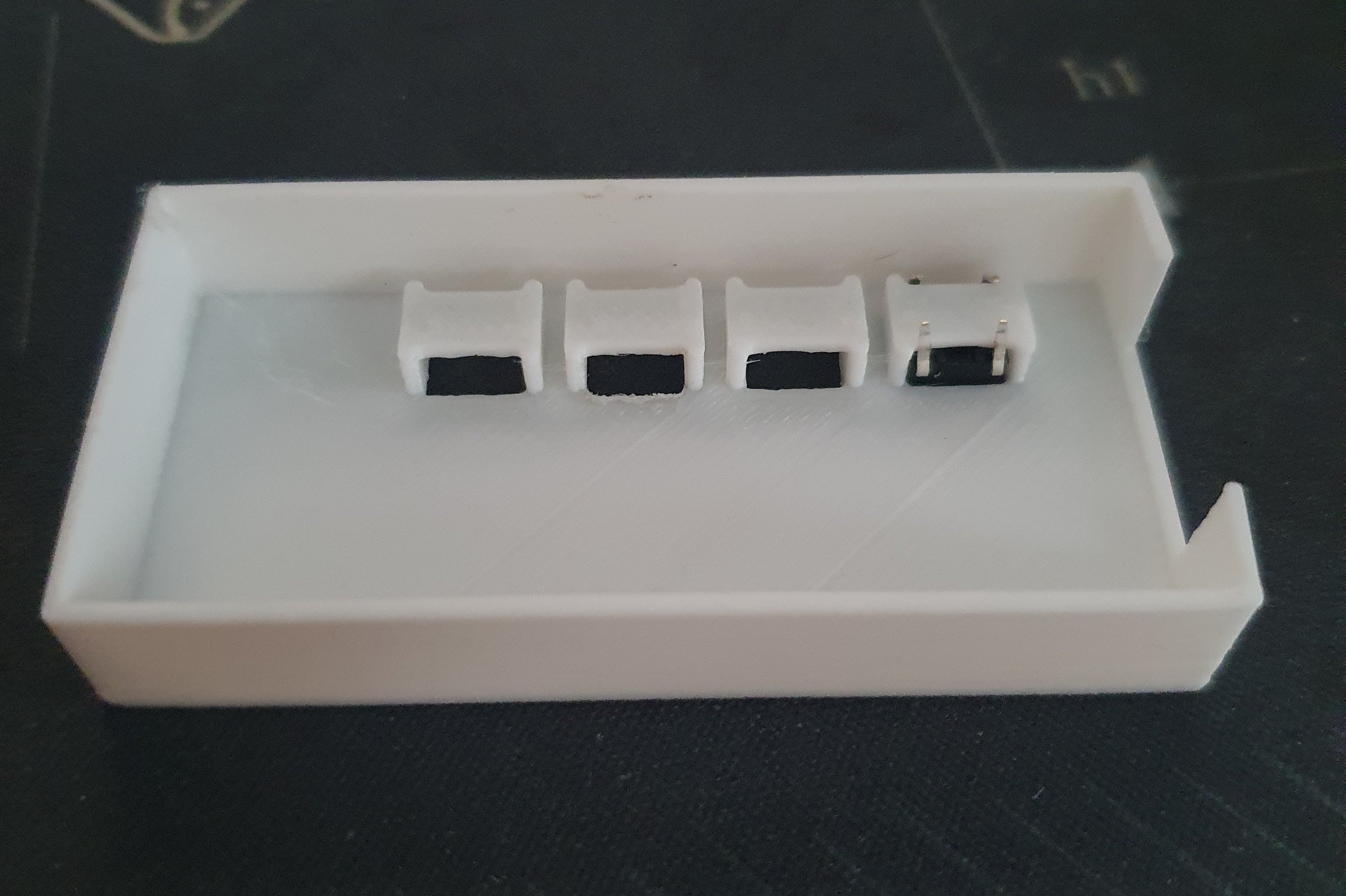
I printed the case on my Ender 3 V3 SE printer. I used PLA and printed it with a 0.2mm layer height and 20% infill. I also used a 0.4mm nozzle. In the previous pictures, you can see the bottom and top of the case. Both fit snuggly and require a bit of force to be put together, but no glue or screws are needed. You can also notice how I handled the buttons, with a slot for them to fit in.
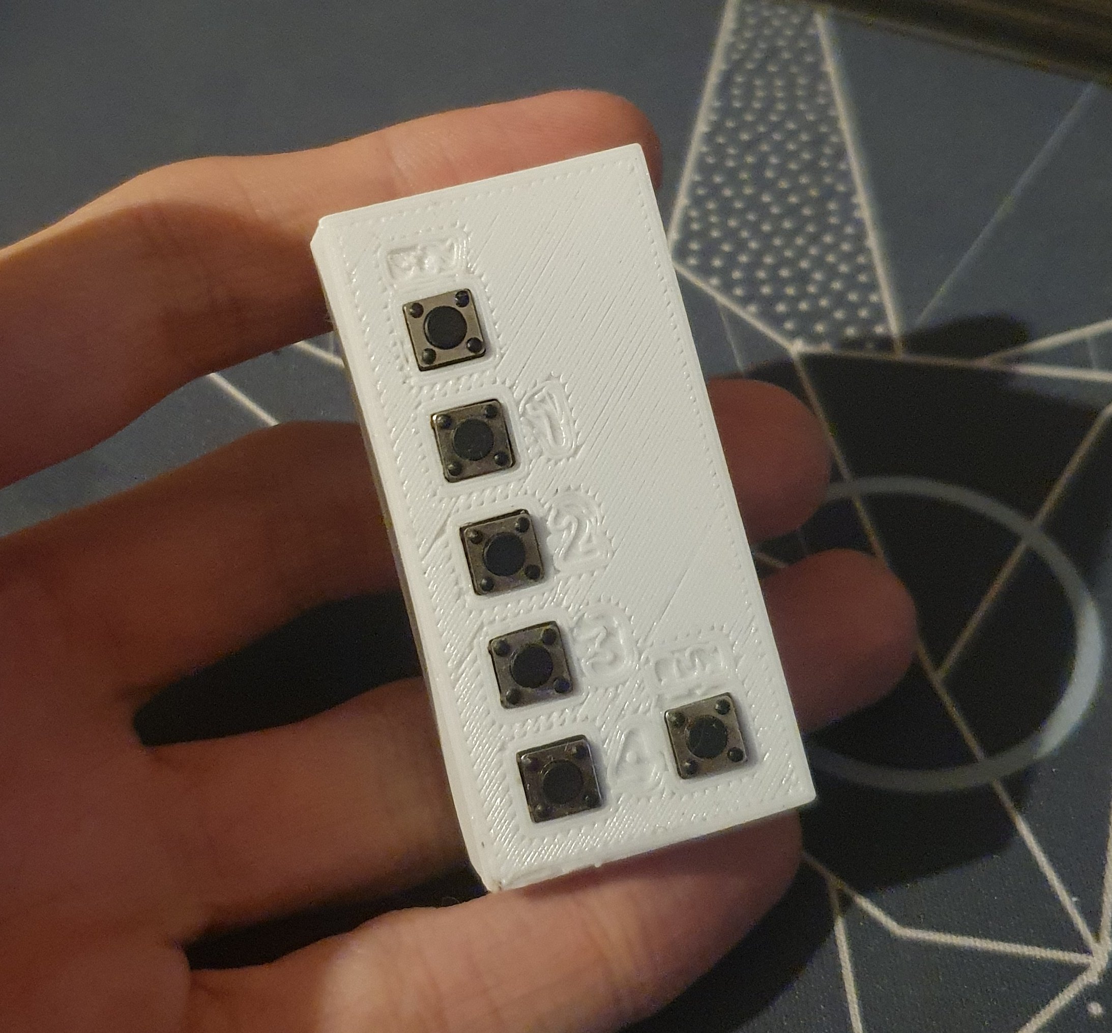 The final case with the pico and the soldered buttons in it
The case is not perfect, but it is good enough for me. Unfortunately, I broke the one that printed well during soldering, so I had to use the one that didn’t print well. I also used small text to indicate the buttons, but it is not readable. You can find the files here.
Final words
Once everything was programmed, printed and assembled, I ended up with the v1 of my pico rubber ducky.
Overall, I’m happy with the result. I got to learn a lot about microcontrollers, CAD and 3d printing. I also got to have a nice gadget that I can use to annoy my friends. I’m not sure if I will use it a lot, but it was a fun project to work on.
I don’t think I will go back to this project either, but I would like to add a little feature that I don’t think exists in the classic duckyscript: breakpoints / resume functions in the script. I think that it could be a nice function to avoid having big delays when you don’t know how long you would have to wait.
If you want to build your own pico-ducky, I provided the links to the differents repositories and parts in the article. I hope you have as much fun as I did building it.
Thanks for reading!
[^1]: DuckyScript is the language used to program Ruber Duckies. I won’t go into much details here, but you can learn more here